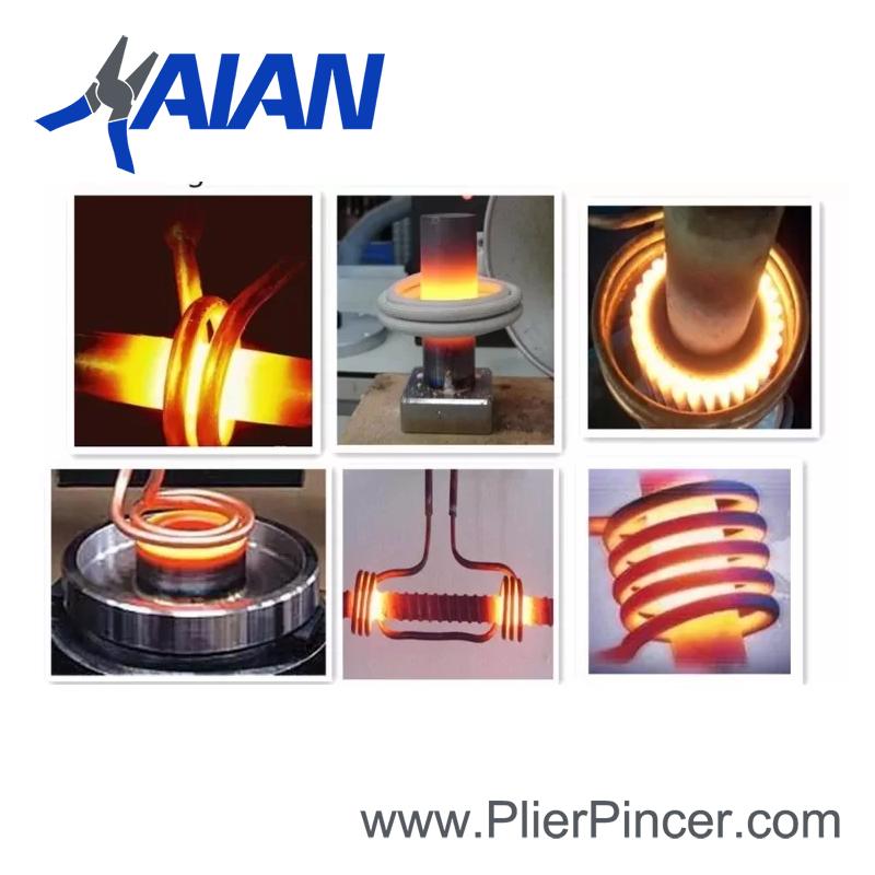
Induction hardening is a method of quickly and selectively hardening the surface of a metal part. A copper coil carrying a significant level of alternating current is placed near (not touching) the part. Heat is generated at, and near the surface by eddy current and hysteresis losses. Quench, usually water-based with an addition such as a polymer, is directed at the part or it is submerged. This transforms the structure to martensite, which is much harder than the prior structure.
A popular, modern type of induction hardening equipment is called a scanner. The part is held between centers, rotated, and passed through a progressive coil which provides both heat and quench. The quench is directed below the coil, so any given area of the part is rapidly cooled immediately following heating. Power level, dwell time, scan (feed) rate and other process variables are precisely controlled by a computer.
Benefits of Induction Hardening
Increased Wear Resistance
There is a direct correlation between hardness and wear resistance. The wear resistance of a part increases significantly with induction hardening, assuming the initial state of the material was either annealed, or treated to a softer condition.
Increased Strength & Fatigue Life due to the Soft Core & Residual Compressive Stress at the Surface
The compressive stress (usually considered a positive attribute) is a result of the hardened structure near the surface occupying slightly more volume than the core and prior structure.
Parts may be Tempered after Induction Hardening to Adjust Hardness Level, as desired
As with any process producing a martensitic structure, tempering will lower hardness while decreasing brittleness.
Deep Case with Tough Core
Typical case depth is .030” – .120” which is deeper on average than processes such as carburizing, carbonitriding, and various forms of nitriding performed at sub-critical temperatures. For certain projects such as axels, or parts which are still useful even after much material has worn away, case depth may be up to ½ inch or greater.
Selective Hardening Process with No Masking Required
Areas with post-welding or post-machining stay soft – very few other heat treat processes are able to achieve this.
Relatively Minimal Distortion
Example: a shaft 1” Ø x 40” long, which has two evenly spaced journals, each 2” long requiring support of a load and wear resistance. Induction hardening is performed on just these surfaces, a total of 4” length. With a conventional method (or if we induction hardened the entire length for that matter), there would be significantly more warpage.
Allows use of Low Cost Steels such as 1045
The most popular steel utilized for parts to be induction hardened is 1045. It is readily machinable, low cost, and due to a carbon content of 0.45% nominal, it may be induction hardened to 58 HRC +. It also has a relatively low risk of cracking during treatment. Other popular materials for this process are 1141/1144, 4140, 4340, ETD150, and various cast irons.
Limitations of Induction Hardening
Requires an Induction Coil and Tooling which relates to the Part’s Geometry
Since the part-to-coil coupling distance is critical to heating efficiency, the coil’s size and contour must be carefully selected. While most treaters have an arsenal of basic coils to heat round shapes such as shafts, pins, rollers etc., some projects may require a custom coil, sometimes costing thousands of dollars. On medium to high volume projects, the benefit of reduced treatment cost per part may easily offset coil cost. In other cases, the engineering benefits of the process may outweigh cost concerns. Otherwise, for low volume projects the coil and tooling cost usually makes the process impractical if a new coil must be built. The part must also be supported in some manner during the treatment. Running between centers is a popular method for shaft type parts, but in many other cases custom tooling must be utilized.
Greater Likelihood of Cracking Compared to most Heat Treatment Processes
This is due to the rapid heating and quenching, also the tendency to create hot spots at features/edges such as: keyways, grooves, cross holes, threads. (Please talk to an AHT representative if you have concerns.)
Distortion with Induction Hardening
Distortion levels do tend to be greater than processes such as ion or gas nitriding, due to the rapid heat/quench and resultant martensitic transformation. That being said, induction hardening may produce less distortion than conventional heat treat, particularly when it’s only applied to a selected area.
Material Limitations with Induction Hardening
Since the induction hardening process does not normally involve diffusion of carbon or other elements, the material must contain enough carbon along with other elements to provide harden ability supporting martensitic transformation to the level of hardness desired. This typically means carbon is in the 0.40%+ range, producing hardness of 56 – 65 HRC. Lower carbon materials such as 8620 may be used with a resultant reduction in achievable hardness (40-45 HRC in this case). Steels such as 1008, 1010, 12L14, 1117 are typically not used due to the limited increase in hardness achievable.
