HAIAN® manufactures the widest and most modern range of locking pliers & clamps worldwide. Continually producing top quality and innovative tools to meet the growing demand of Welding, Metal Work, Maintenance, Pipe, Auto Mechanics, Auto Body, DIY, Woodworking, Retail and Multi-use.
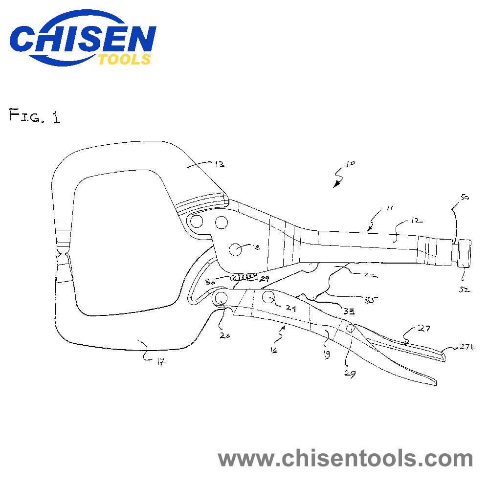
The locking pliers comprises a first handle connected to a first jaw. A second handle and second jaw are pivotably connected to the first handle and first jaw such that movement of the first handle relative to the second handle causes the jaws to open and close. A mechanism is provided to lock the jaws relative to one another and apply a clamping or gripping force on a workpiece positioned between the jaws. A release mechanism is provided to unlock the pliers that is independent of the locking operation.
Claims
1. A lockable pliers comprising:
a first handle supporting a first jaw;
a second handle movable relative to the first handle between an open position and a closed, locked position;
a second jaw movable between a first position when said second handle is in said open position and a second position when said second handle is in said closed position;
a locking mechanism having a link for locking the second jaw in the second position;
a stop formed on said link for engaging the second handle and limiting movement of the locking mechanism relative to said second handle when the second handle is in the closed, locked position; and
a release lever pivotably connected to said second handle and including a portion located in a space between said locking mechanism and said second handle, said release lever and said space being dimensioned such that the portion of the release lever is not trapped between said second handle and said locking mechanism such that said release lever may move slightly between said second handle and said locking mechanism when said second handle is in the closed, locked position.
2. The locking pliers of claim 1 wherein an adjustment screw changes the geometry of the locking mechanism.
3. The locking pliers of claim 1 wherein a protrusion is formed on said link for being contacted by said release lever.
4. The locking pliers of claim 3 wherein said protrusion is separate from said stop.
5. The locking pliers of claim 4 wherein said protrusion forms a single projection with said stop.
6. The locking pliers of claim 5 wherein said stop extends from said link a greater distance than said protrusion.
7. The locking pliers of claim 4 wherein the protrusion extends from said release lever.
8. A method of making a lockable pliers comprising:
providing a first handle supporting a first jaw;
providing a second handle movable relative to the first handle between an open position and a closed, locked position and a second jaw movable between a first position when said second handle is in said open position and a second position when said second handle is in said closed position;
providing a locking mechanism having a link for locking the second jaw in the second position;
forming a stop on said link for engaging the second handle and limiting the movement of the locking mechanism relative to the second handle when the second handle is in the closed, locked position;
pivotably mounting a release lever on said second handle such that a portion of the release member is located in a space between said locking mechanism and said second handle, dimensioning said release lever and said space such that the portion of the release level is not trapped between said second handle and said locking mechanism such that said release lever may move slightly between said second handle and said locking mechanism when said second handle is in the closed, locked position.
9. A lockable pliers comprising:
a first handle supporting a first jaw;
a second handle movable relative to the first handle between an open position and a closed, locked position;
a second jaw movable between a first position when said second handle is in said open position and a second position when said second handle is in said closed position;
a locking mechanism having a link for locking the second jaw in the second position;
a stop formed on said second handle for engaging the link and limiting movement of the locking mechanism relative to said second handle when the second handle is in the closed, locked position; and
a release lever pivotably connected to said second handle and including a portion located in a space between said locking mechanism and said second handle, said release lever and said space being dimensioned such that the portion of the release lever is not trapped between said second handle and said locking mechanism such that said release lever may move slightly between said second handle and said locking mechanism when said second handle is in the closed, locked position.
Description
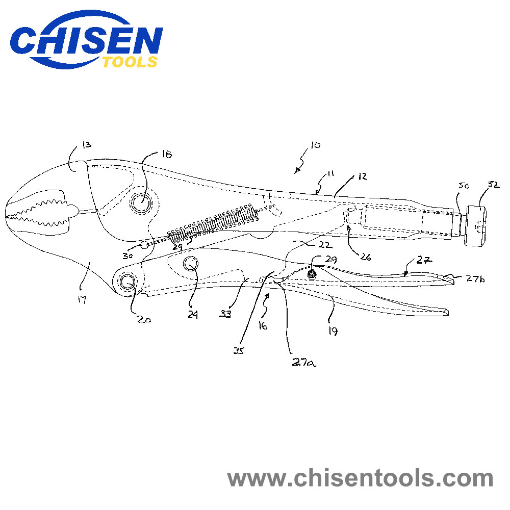
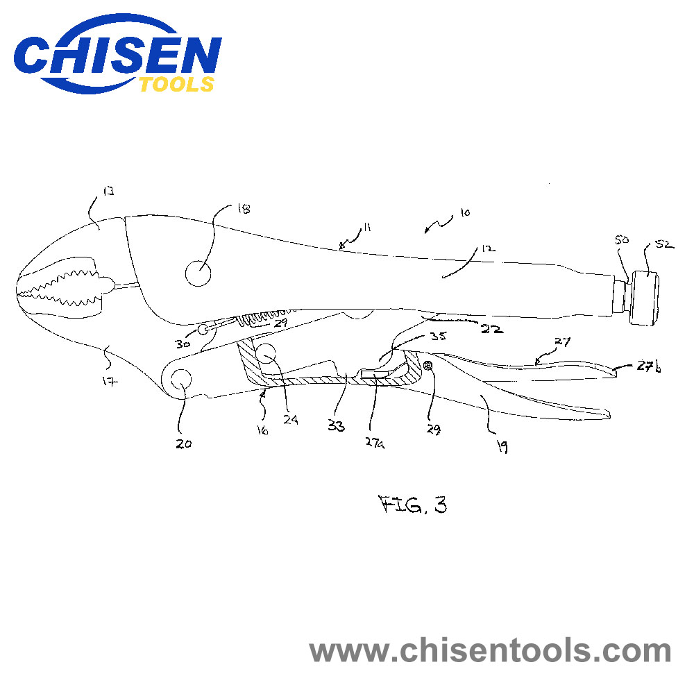
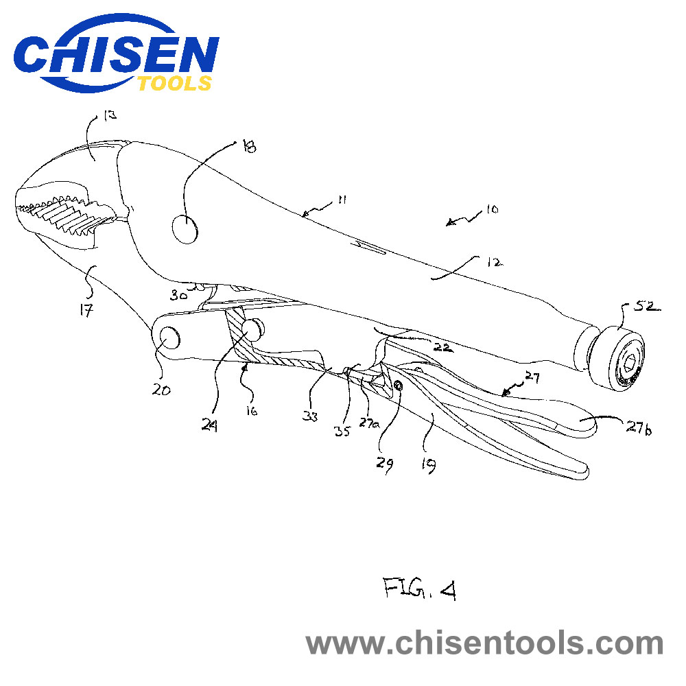
While a simple toggle-locking mechanism comprising a single-link 22 is shown, it is to be understood that the toggle-locking mechanism may comprise other configurations including compound toggle-linking mechanisms and/or self-adjusting mechanisms. A biasing spring 29 extends from a hole 30 on the movable jaw 17 to the fixed arm 11. The spring 29 applies a bias which tends to separate the handles 12 and 19 from one another and open jaws 13 and 17.
When the jaws 13 and 17 are in the open position, the pivot points, 18, 20, 24 and 26 are arranged as a polygon. When the jaws are in the closed, locked position as shown in FIG. 2, the pivots 20, 24 and 26 are substantially in a straight line where pin 24 is slightly over-center, toward fixed arm 11, of a line between pivots 20 and 26. The link 22 is prevented from moving closer to the fixed handle 12 because the stop 33 of link 22 presses against the arm 16.
The “throw” of the linkage is the distance the linkage moves from the unlocked position to the locked over-center clamping position. When the work piece is clamped between the jaws and increasing force is applied to the handles 12 and 19, the forces generated on the linkage cause link 22 to pivot and the linkage begins to straighten and the effective length of the linkage between pivots 20 and 26 increases. As the effective length of the linkage increases, increasing force must be applied to the handles 12 and 19 to move the linkage to the over-center locked position. This force is transmitted through the pliers to the work piece to increase the clamping force generated by the jaws on the work piece. Typically, the greater the throw the greater the force applied by the pliers.
It should be further understood that the “over-center” condition of the pivots 20, 24 and 26, which maintains the jaws in a locked position, also includes an arrangement where pins 20, 24 and 26 are aligned “dead center,” that is, in a straight line. Any configuration of pivot pins and stops, for example, the stop 33, which places the mechanism in a locked position when the jaws are closed or grasping a workpiece, can be considered an over-center mechanism when force applied directly to the jaws to separate the jaws is not effective in moving the jaws and the jaws can only be opened by forces acting on the links of the mechanism.
Screw 50 is located in the fixed handle such that the longitudinal axis of the screw is disposed along and located in the fixed arm 11. The screw 50 is formed with an enlarged head 52 that can be manually rotated to adjust the locking pliers. The screw is operatively connected to the end of linkage 22 to create pivot 26 such that it can be used to control the effective length of the linkage and thereby the force applied by the pliers in the locked position.
Once locked, the jaws 13 and 17 cannot be pried apart from the locked position by a force acting on the jaws 13, 17 because separation of the jaws is prevented by the over-center condition of the pivots 20, 24 and 26. However, the jaws 13, 17 may be separated by applying a force to the movable handle 19 in a direction which moves the movable handle 19 away from the fixed handle 12. Depending on the amount of force generated through the pliers in the locked position, the force applied to the handles to open the pliers may be relatively large.
A release mechanism is provided to facilitate opening of the jaws. Specifically, lever 27 is pivotably connected to arm 16 at pivot pin 29. As previously explained stop 33 directly contacts the movable arm 16 to limit the movement of the linkage in the locked position. The end 27a of lever 27 is disposed between link 22 and movable arm 16 when the jaws are in the closed and locked position but the link 22 does not contact stop 33. Because the movement of the linkage is limited by direct contact between the arm 16 and the link 22 the lever 27 does not affect the throw of the tool.
The end 27a of lever 27 cooperates with protrusion 35 to release the jaws. Specifically, in the locked position the end 27a of lever 27 is disposed between the protrusion 35 and the movable arm 16 but the lever 27 is not trapped between these elements such that the lever 27 may move slightly between the protrusion 35 and arm 16. Thus, lever 27 has no affect on the stop or locked position of link 22 and therefore has no effect on the clamping force exerted by the jaws 13 and 17. The stop position of link 22 and the locked position of the pliers are controlled by the engagement of stop 33 with arm 16.
By pushing on the opposite end 27b of lever 27, lever 27 pivots about pivot pin 29 forcing end 27a away from handle 19 to contact link 22 at protrusion 35. The force exerted by lever 27 on protrusion 35 is sufficient to move link 22 and release the locking mechanism.
The pliers discussed with reference to the Figures use a push type release lever where one end of the lever is pushed toward the handle 19 to force the opposite end of the lever into engagement with the link 22. The locking mechanism of the invention may also be used with pull type release levers where the lever is pulled away from handle 19 and into engagement with link 22.
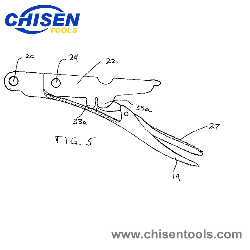
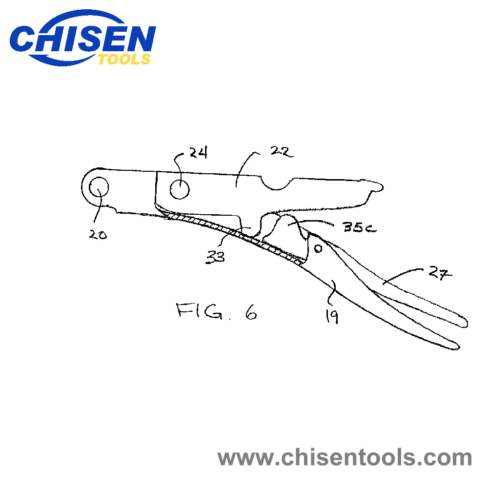
In the embodiment shown in FIGS. 1 through 5 the stop 33 and protrusion 35 are formed on link 22 closely adjacent one another such that a single continuous projection extends from link 22. In an alternate embodiment the stop 33a and the protrusion 35a may be separated in distance such that two projections are formed on link 22 as shown in FIG. 6. Further, while the protrusion 35 and stop 33 as shown as being formed integrally with link 22, these elements may be formed as separate components that are attached to link 22. Finally, the protrusion 35c may be formed on the lever 27 rather than on link 22 a shown in FIG. 7.
Specific embodiments of an invention are disclosed herein. One of ordinary skill in the art will recognize that the invention has other applications in other environments. Many embodiments are possible. The following claims are in no way intended to limit the scope of the invention to the specific embodiments described above.
How to Use Locking Pliers
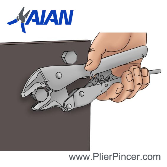
Locking pliers, sometimes referred to as vise-grips depending on the style of locking mechanism they incorporate, are great tools to keep handy. Typically, locking pliers are used where more torque is needed to pry or remove objects or where added grip is needed for holding objects in place. Most uses includes loosening tight connection points such as pipe-joints, seized nuts and washers and removing broken nails. Using locking pliers will greatly reduce the amount of strain you have to apply when trying to loosen connection points or remove stuck metal objects.
Step 1
Open the pliers up completely. Do this by pulling the handles away from each other.
Step 2
Locate teh plier mouth adjustment bolt. This is a round screw-head at the bottom of one handle. Unsrew the bolt counterclockwise to widen the gripping mouth for large objects, or screw clockwise to adjust to smaller objects.
Step 3
Place the gripping mounth on the object to size for adjustment. If you place the pliers onto the object and squeeze the handles together and the pliers don’t lock, then you need to adjust the mouth wider.
Step 4
Squeeze the handles together untill you hear a click. The locking plate should no longer be flush with the pliers handle. This is a piece of metal that will pop out in between the handles when locked properly.
Step 5
Push the locking plate down flush with the handle to unlock the pliers.
10 Everyday Uses for Locking Pliers
The first locking pliers as we know them today were invented in 1924 by a blacksmith called William Petersen. He christened them Vise-Grips, and the range continues to be manufactured to this day as part of the Irwin brand. Given the high levels of clamping force afforded by these compact hand tools, Petersen’s choice of name was apt, and has endured as a generic term for all brands of locking pliers. Since they were originally introduced, a huge number of design variations have appeared on the market from just about every hand tool manufacturer on the planet, and they are widely regarded as some of the most useful and versatile hand tools available. In this article we will look at some everyday practical uses for locking pliers which have resulted in them becoming an essential component in the household and professional tool kit alike.
Locking Pliers – How they work
If you’ve never used a pair of locking pliers before, they all operate on the same basic principle: a screw at the back of the tool is used to adjust the spacing of the jaws, and it usually takes a few seconds of trial and error to achieve the required setting for whatever object you want the pliers to grip. When the optimum setting has been dialed in, the jaws will close together with an audible “click”, and lock in place. Once locked in place, the pliers literally grip material like a vice; to release the jaws, there is a separate lever built into the handle which instantly disengages them when it is pressed.
Locking Pliers – Uses
Locking pliers are something of a unique tool, being derived from both vices and pliers (as a blacksmith, Petersen had become frustrated by the limitations of the vices and pliers in his workshop and had the idea that he could combine the best features of both into one device). As a result, they can be used for many applications that either clamps or pliers would be used for, as well as numerous other applications that hardly any other tool would be suitable for. Let’s take a look at some of the most common uses.
1. Clamping
The locking vice grip that is characteristic of these tools makes them a go-to solution for many clamping applications; some locking pliers are designed exclusively for clamping purposes, but all variants are suitable for this job. The heavy duty metal construction of locking pliers means they are especially favoured amongst welders, and it is common to find specialized locking pliers intended for the metalworking industry. Locking pliers are also useful for firmly clamping jigs and components in woodworking applications, but bear in mind they can easily damage bare wood if clamped directly onto it.
2. Holing
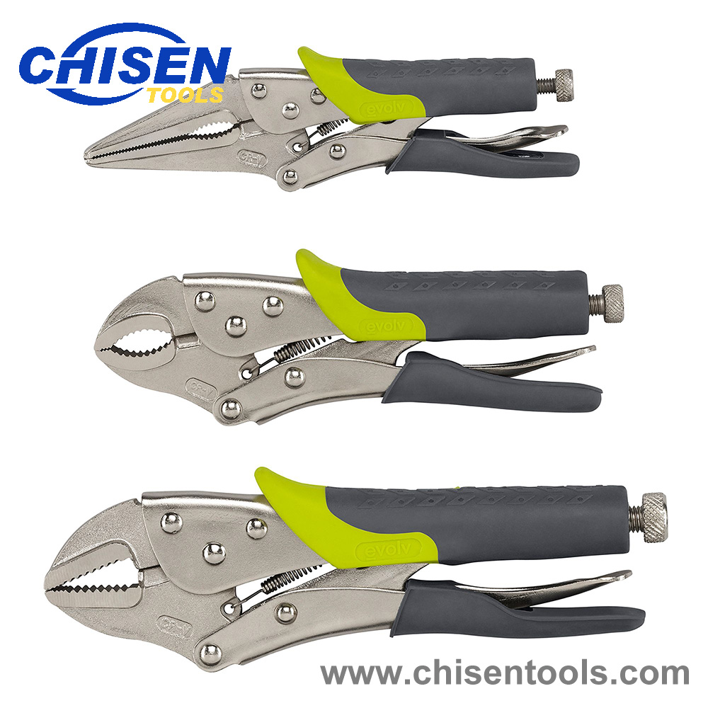
Locking pliers can be used to handle materials whenever it would be awkward or uncomfortable to grip them directly, for instance when working with heat or maneuvering small components into position for gluing or soldering. Long nose locking pliers are some of the most common tools for precision applications, and their tapered jaws enable the user to access more cramped workspaces and recessed areas.
3. Pulling Nails, Staples & and other Fasteners
Because they clamp down on objects with considerable force, locking pliers can be used to extract stubborn nails and other fasteners where many standard pliers would struggle to provide sufficient hold under pressure. They are especially useful for extracting broken fasteners where there is no head to facilitate levering with a pry bar or claw hammer.
4. Extracting Rounded Nuts & Bolts
Similarly, if a nut or bolt has become sufficiently rounded that there is no chance of getting a spanner or socket to fit it, locking pliers can be used to grip the damaged part and turn the component in its threads, enabling the fastener to be removed (or tightened if necessary). If you are in a tight spot and there are no spanners or sockets available, locking pliers can also be used to drive undamaged nuts or bolts too. This can cause increased wear to fasteners so is not usually recommended except as a last resort; however some types of locking pliers have jaws which are designed with hex bolts in mind, and suitability can vary from model to model.
5. Replacing a Broken Knob or Lever
In the event that a knob, lever or other control handle is damaged or removed from a piece of apparatus, the operator is often faced with an unergonomic stub or shaft that can be difficult or impossible to turn by hand, especially if it is recessed or otherwise hard to access. Locking pliers make ideal replacement handles in these situations; once locked securely in place, they will generally enable sufficient turning or levering force to be applied to restore functionality until the component can be repaired or replaced.
6. Wire Cutting
Though it is not a universal design feature, a great deal of locking pliers are built with an additional function built into the rear section of the jaws: an integrated wire cutter, which makes them a practical tool for snipping wire as well as bending, shaping and holding it. These cutters can also be used on pallet strapping, string, cable ties and various other materials.
7. Pinching off Pipes, Lines and Tubes
If you need to squeeze a tube or pipeline closed, e.g to suppress a leak or temporarily shut off a system for maintenance or repair, locking pliers make a quick and easy solution. Many of the commonly available types of locking plier will be suitable for this application in a pinch (pun intended) but professional plumbers, mechanics and maintenance engineers will often buy specialized variants like the Irwin Vise Grip Locking Pinch Off Tool, which was developed specifically for the requirements of the refrigeration industry.
8. Driving Screw
If you find you’ve broken or misplaced your trusty screwdriver handle in the middle of a job, locking pliers can be pressed into service as an emergency screwdriver bit holder. Simply lock the bit in place between the jaws and it will be held securely enough to apply ample torque for most light duty applications. It’s not the most ergonomic solution but it works well enough to finish off a half driven screw or remove a couple of fasteners in a hurry.
9. Light Duty Demolition and Shaping Tasks
If you need to bend or break materials like plastic and thin metals, locking pliers can be a useful piece of kit. The locking jaws do the gripping for you, enabling you to put more energy into twisting, levering and prying. Smaller long nose types are ideal for gripping material in awkward spaces, while larger models enable greater force to be applied for more heavy duty work. As well as greatly increasing the strength it would be possible to employ by hand alone, using pliers also ensures there is less risk of being injured by any sharp edges encountered in the process.
10. Pressing and Squeezing
Due to the force they are able to exert, locking pliers can also be used for fixing or assembling components like chain links and for crimping wire connectors.
Conclusion
There’s no doubt that locking pliers are just about the most versatile hand tools available and this article only covers a handful of typical everyday uses for them. Check out the categories below to see the full range we stock at Tooled-up, and if you have any unique or ingenious uses for them that aren’t covered in this blog post then let us know in the comments!